Slop fired Boiler bag filter commissioning & shutdown procedure


Pre-Coating & Pre-heating

  • Box – up the bag house and close all access doors properly.
  • Keep the module outlet damper full open.
  • Close the Bypass dampers 100%.
  • Close the inlet damper 100%.
  • Make sure that the lime injection system is ready
  • Run the ID Fan and adjust the fan controls for effective suction for pre coating. (the air will flow from the boiler section .If required doors in the economizer section can be opened to draw fresh air into the bag filter)
  • Run the ID Fan and adjust the fan controls for effective suction for pre coating. (the air will flow from the boiler section .If required doors in the economizer section can be opened to draw fresh air into the bag filter)
  • Switch ON the lime injection system and start lime spray into the inlet duct. (Note : Dolomite powder can be used for pre coating)
  • Do not start pulsing during this period.
  • Observe the change in Differential pressure across the tube sheet.
  • After sufficient pre coating, as observed from the Diff Pressure gauge, around 10-  15 mmWG increases, stop the pre coating. Record the readings.
  • Stop the ID fan.
  • Switch on the hopper heaters
  • Switch on the Close Circuit heating system as follows
  • Close the bag filter inlet & outlet dampers.
  • Open the heating system inlet and outlet valves.
  • Start the blower.
  • Switch on the heaters.
  • Allow the hot air circulation to push up the internal temp > 140 Deg C (Approx).

Bag filter start up

  • Open the Bypass dampers both multi lower and puppet dampers by 100%
  • Keep Bag filter inlet and outlet dampers closed.
  • Ensure that the operation of dust conveying system below the hoppers is checked thoroughly and should be kept in operation
  • Light up the boiler and take the exhaust gases through the bypass path.
  • Continue with only coal firing.
  • Once the gas temperature reaches 140 Deg C +, then take the bag filter in line
  • Keep the BF pulsing OFF from the beginning
  • Open the bag filter inlet and outlet dampers 100%
  • Start closing the multi lower damper in the bypass line gradually, by maintaining the furnace pressure. This will divert the gas gradually through the bag filter. The ID fan speed will go up gradually. This process will take some time
  • When the entire gas is diverted through the bag filter and the multi lower damper in the bypass line is fully closed, and then close the puppet damper in the bypass line fully. (Caution: If the bypass dampers is not fully closed then the dust gases can escape to the stack through this route and push up the emission level).
  • Continue Coal firing and allow Bag filter inlet temperature to cross 180 Deg C.
  • Put the Bag pulsing in demand cleaning mode – Cleaning to start at 175 mmWG and stop at 150 mmWG. This can be readjusted if required.
  • Adjust the pulse air pressure to 3.5 Kg/Cm2.
  • Adjust Sol. Valve ON time 100 msec , OFF time 25 Sec (to start with)
  • Start spent wash firing and increase it gradually in small steps. (Caution: Sudden increase in spent wash firing rate can lead to clinker formation in boiler and chocking of bags in the filter.)
  • Start the lime injection system ( Quantity : Lime powder with 50 to 150 microns mesh size @ 150 kg/Hr)
  • Restrict the bag filter inlet temp between 180 – 220 Deg C (Max 240 DegC for ½ Hr).
  • Record all readings every one hour as given in the log sheet.

Bag filter shut down

Slop fired boiler start up procedure

  • After shutdown or tripping the boiler follow following procedures to shutdown bag filter
  • Start opening the puppet


    damper fully, after full opening of puppet damper, slowly start opening regulating damper adjusting the furnace pressure & ensure full opening of the damper.
  • Close inlet and outlet dampers of the bag filter.
  • Keep the pulsing on through timer mode for around ½ hr to dislodge the dust from the bags when the inside temp is high (Caution: Do not pulse the bags when the inside temp is low this may clog the bags.
  • Keep the hoper heaters ON.
  • Open the inlet and outlet valves of the heating system.
  • Start the heating system fan & heater to keep the internal temp to above 140Deg C for ½ hr, till the bag pulsing is over. Keep the dust conveying system ON for at least 1 hr to remove all the dust from the hopper.
  • After ½ hour a) Stop the bag pulsing b) Stop the close Circuit heating system. c) Stop the hopper heating system
  • Allow the bag filter to cool down in boxed up condition before opening the access doors. Then open the access doors and allow the natural purging before entering inside the filter. 

Questions & Answers on Ash handling system

1.What is Ash?

Ash is the remaining product of solid or liquid fuel after burning

2.What are the various components of Ash?

Ash has following components

  • Silica (SiO2)
  • Alumina (AlO3)
  • Iron Oxide (Fe2O3)
  • Sodium Oxide (Na2O)
  • Potassium Oxide (K2O)
  • Calcium Oxide (CaO2)
  • Magnesia (MgO)

3.Which fuel has more ash Liquid, solid or Gaseous fuel?

Solid, Liquid & Gaseous fuels are having more ash consecutively

4.What are the various types of ash produced in Boilers?

Bottom ash & Fly ash are generated in Boilers

5.Which ash is more in quantity?

Generally Fly ash is more around 70-80% & bottom ash is around 20-30%

6.What do you mean by Fly ash?

Ash which is carried out by flue gas is called fly ash.

7.What can fly ash could cause in downstream system of The Boiler?

  • If ash is more, it creates following problems in downstream of the Boiler
  • Improper heat transfer in Super heaters, economizers & APH
  • Erosion of pressure parts & flue gas ducts
  • If there is low velocity, ash deposits in ducts, APH ESP etc

8.Which type of Ash removal is more dangerous & why?

  • Bottom ash removal is more dangerous, because;
  • Bottom Ash is at higher temperature
  • Ash is high Abrasive & Corrosive in Nature
  • When it comes in contact with water high hot fumes are formed
  • Risk of frequent clinker formation

9.What are the different devices or systems used to separate Fly ash from flue gas before letting it into atmosphere?

  • Electrostatic Precipitator
  • Bag filter (Fabric separators)
  • Wet scrubber
  • Inertial separators (Settling chamber, Baffle chambers, Cyclone separator)
  • Fabric hybrid filter

10.Briefly explain the Fabric Separator type bag filters

In this system, fabric bags are used to filter the flue gas to separate the dust. Dust laden gases enter the bag house and passes through fabric bags which act as filter.The bags are woven with material nylon, fiber glass etc. Each bag is externally supported by steel/metal cage. The bag filter house is provided with an explosion vent to avoid explosion during abnormal operation conditions.

Further, the bag filter house consists of hoppers & ash handling system to remove fly ash separated in bag filters.

In bag filters, the dust collects at the outer surface of the bag since flue gas flow from out side to inside of the bag.

Mechanism of dust collection:

Gravity: Due to gravitational force & sudden lower velocity large sized dust/ash particles fall down into hopper due to Gravitational force.

Inertial collection: Due to inertial, heavy dust particles strike the bag filters placed in the flue gas path & fall down into the hopper, since they do not change their flow direction due to inertia.

Interception: Due to the fine mesh or size of the bag filters, dust or ash particles cannot cross the filters. Instead they hit filters & fall down into the hopper.

Electrostatic effect: Electrostatic force between dust particles & bag filter causes the dust to capture.

11.How do you remove dust particles from Bag filters?

  • Mechanical Shaker
  • Reverse air
  • Reverse Jet

12.What are the various materials of composition (MOC) of Bag filters?

Sl No.

Bag filter material

Operating temperature (0C)

1

Nylon

85-90

2

Polyester

130-140

3

Polyphenylene  sulphide or Ryton

180-190

4

Fibre glass

250-260

5

Fibre glass fabric coated with PTFE

250-260

13.What are the various factors considered for selection of Bag filters?

  • Flue gas temperature
  • Moisture level in flue gas
  • Dust or ash particles size
  • O2% in flue gas
  • Flue gas velocity
  • Dust or ash particles abrasiveness
  • Air to cloth ratio

14.What are the main functions of Ash handling system?

  • To remove the ash from Boiler furnace & other various ash discharge points
  • To convey this ash to nearby storage area like ash silo
  • Ash disposing

15.What are the various types of Ash handling systems used in Boilers?

Mechanical ash handling system: In this system chain, belt & screw conveyors are used to convey the ash from various ash termination points to ash silo.


Pneumatic ash handling system:


Pneumatic ash handling system is used widely in most of the Power plants. High pressure air is used to convey the ash to the suitable location.

16.What are the various types of Pneumatic ash handling systems used in Boilers/power plants?

  • Lean phase ash handling system
  • Medium phase
  • Dense phase

17.Why dense phase ash handling system is used in almost all Boilers Ash handling plant?

Because it has less air consumption due to volumetric ration of air & ash is more. Sometimes instead of pressurized air vacuum system is used to convey the ash.

Briefly explain the dense phase Ash handling system

In this system, Ash conveying system is placed just below the ash hopper. This system consists of Main ash hopper

  • Surge hopper with electromagnetic or Mechanical vibrators
  • Knife edge gate valve
  • SS expansion bellow
  • Dome valve assembly & operating mechanism
  • Ash & air conveying valves, solenoid valves
  • Pressure switches & limit switches
  • Conveying pipelines

If the temperature of the ash is more (Economiser & APH) surge hopper is made with water jacket for continuous circulation of water.

The system can be operated from local & remote in probe mode or timer mode.

Calculation part:

1. A Boiler is consuming 72 TPH an imported coal having ash % 8, calculate the total ash generated in a complete month. Assume there is no stoppages or load fluctuation

Total coal consumed in a month = 72 X 24 X 30 = 51840 MT

Total ash generated in a month = 51840 X 8 / 100 = 4147.2 MT

2. A boiler consumes 7 TPH of coal, calculate the total fly ash generated in a day if coal has 35% ash.

Total ash generated = 7 X 24 X 35 / 100 = 58.8 MT

We know that, fly ash is around 80% of total ash.

So total fly ash generated is 58.8 X 80 / 100 = 47.04 MT

3. A Boiler generates 20 MT of ash in a day, calculate total coal consumed in a day if coal has 5% of ash in it

Total ash generated =20 MT/day

Ash % in coal = 5%

Therefore total coal consumed = 20  / 5% = 400 MT


 For related articles read Power plant & Calculations


boAt Rockerz 255 Pro+ Bluetooth Wireless in Ear Earphones with Mic (Teal Green)


Questions & Answers on steam Blowing


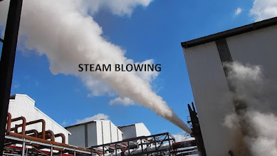
1.What is the purpose of steam blowing?

The purpose of the steam blowing is to remove any foreign materials from steam piping & super heater coils after completion of erection work.

2.What will happen if steam blowing is not done after erection or repair of Boiler?

If steam blowing is not done, considerable damage will happen to the steam lines & other end user applications like steam turbine, process heat exchangers due to scale, debris & other foreign materials present in the newly erected pipe lines/coils.

3.What is the basis behind steam blowing?

The basis behind the steam blowing is to create momentum equal to or preferably greater than that during normal operation. This will blow out all the debris from the steam lines

4.What are the two different methods of steam blowing?

Puff method & continuous method. In puff method thermal shock is created & in continuous steam blowing, constant steam purge is maintained

5.What are the requirements for steam blowing for newly erected Boilers?

  1. Steam blowing area is corned off & notice board or caution board should be displayed
  2. Ensure Boiler hydraulic test, alkali boil out & passivation procedures are completed before steam blowing
  3. All the temporary supports used during erection should be removed
  4. Steam pipe lines & valves used for steam blowing line should be equal to the maximum size of permanent pipe.
  5. Sharp elbows, bends & tees should be avoided in steam blowing pipe line to avoid more pressure drop
  6. Temporary pipe lines used for blowing should be well supported to withstand reaction forces created during steam blowing.
  7. Steam blowing line should be terminated outside the Turbine hall or process
  8. Sufficient allowance should be given to steam blowing line for thermal expansion
  9. Ensure steam line supports & hangers are erected & set properly
  10. Ensure control valves, steam nozzles & NRV flops are not installed during steam blowing
  11. Initially steam blowing is done at lower mass flow

6.What is the time gap between two steam blows?

For an un insulated steam pipe line blowing can be done at every 1 hr. And for insulated steam pile line the gap between two blows should be 3–4 hours

7.Which materials are used for target plates?

Aluminum & stain less steel

8.How do you decide the steam is clear after blowing?

 If there are only two or less than two recognizable impressions found on per square centimeter of target plate, then the target plate is said to be clean.

For Target Plate Made of Aluminum:

The piping considered clean if there are not more than 3 (Three) pitting of 0.5 mm to 1mm dia. in center area of 25 mm X 25 mm and shall not have any deformed edges. Besides this there shall be no pitting in the rim zone. Pitting below 0.5 mm may be ignored.

For Target Plate Made of Stainless Steel:

 The piping is considered clean if there are not more than five pitting of 0.1 mm dia to 0.5 mm dia. in center area of 50 mm X 50 mm & shall not have any deformed edges. Pitting below 0.1 mm may be ignored 

Read reference books for power plant O&M

For more related articles on power plant

Read

Power plant & Calculations

15-Emergencies in power plant operation

Most visited posts