Showing posts with label Boiler. Show all posts

Questions & Answers on Ash handling system

1.What is Ash?

Ash is the remaining product of solid or liquid fuel after burning

2.What are the various components of Ash?

Ash has following components

  • Silica (SiO2)
  • Alumina (AlO3)
  • Iron Oxide (Fe2O3)
  • Sodium Oxide (Na2O)
  • Potassium Oxide (K2O)
  • Calcium Oxide (CaO2)
  • Magnesia (MgO)

3.Which fuel has more ash Liquid, solid or Gaseous fuel?

Solid, Liquid & Gaseous fuels are having more ash consecutively

4.What are the various types of ash produced in Boilers?

Bottom ash & Fly ash are generated in Boilers

5.Which ash is more in quantity?

Generally Fly ash is more around 70-80% & bottom ash is around 20-30%

6.What do you mean by Fly ash?

Ash which is carried out by flue gas is called fly ash.

7.What can fly ash could cause in downstream system of The Boiler?

  • If ash is more, it creates following problems in downstream of the Boiler
  • Improper heat transfer in Super heaters, economizers & APH
  • Erosion of pressure parts & flue gas ducts
  • If there is low velocity, ash deposits in ducts, APH ESP etc

8.Which type of Ash removal is more dangerous & why?

  • Bottom ash removal is more dangerous, because;
  • Bottom Ash is at higher temperature
  • Ash is high Abrasive & Corrosive in Nature
  • When it comes in contact with water high hot fumes are formed
  • Risk of frequent clinker formation

9.What are the different devices or systems used to separate Fly ash from flue gas before letting it into atmosphere?

  • Electrostatic Precipitator
  • Bag filter (Fabric separators)
  • Wet scrubber
  • Inertial separators (Settling chamber, Baffle chambers, Cyclone separator)
  • Fabric hybrid filter

10.Briefly explain the Fabric Separator type bag filters

In this system, fabric bags are used to filter the flue gas to separate the dust. Dust laden gases enter the bag house and passes through fabric bags which act as filter.The bags are woven with material nylon, fiber glass etc. Each bag is externally supported by steel/metal cage. The bag filter house is provided with an explosion vent to avoid explosion during abnormal operation conditions.

Further, the bag filter house consists of hoppers & ash handling system to remove fly ash separated in bag filters.

In bag filters, the dust collects at the outer surface of the bag since flue gas flow from out side to inside of the bag.

Mechanism of dust collection:

Gravity: Due to gravitational force & sudden lower velocity large sized dust/ash particles fall down into hopper due to Gravitational force.

Inertial collection: Due to inertial, heavy dust particles strike the bag filters placed in the flue gas path & fall down into the hopper, since they do not change their flow direction due to inertia.

Interception: Due to the fine mesh or size of the bag filters, dust or ash particles cannot cross the filters. Instead they hit filters & fall down into the hopper.

Electrostatic effect: Electrostatic force between dust particles & bag filter causes the dust to capture.

11.How do you remove dust particles from Bag filters?

  • Mechanical Shaker
  • Reverse air
  • Reverse Jet

12.What are the various materials of composition (MOC) of Bag filters?

Sl No.

Bag filter material

Operating temperature (0C)

1

Nylon

85-90

2

Polyester

130-140

3

Polyphenylene  sulphide or Ryton

180-190

4

Fibre glass

250-260

5

Fibre glass fabric coated with PTFE

250-260

13.What are the various factors considered for selection of Bag filters?

  • Flue gas temperature
  • Moisture level in flue gas
  • Dust or ash particles size
  • O2% in flue gas
  • Flue gas velocity
  • Dust or ash particles abrasiveness
  • Air to cloth ratio

14.What are the main functions of Ash handling system?

  • To remove the ash from Boiler furnace & other various ash discharge points
  • To convey this ash to nearby storage area like ash silo
  • Ash disposing

15.What are the various types of Ash handling systems used in Boilers?

Mechanical ash handling system: In this system chain, belt & screw conveyors are used to convey the ash from various ash termination points to ash silo.


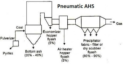
Pneumatic ash handling system:


Pneumatic ash handling system is used widely in most of the Power plants. High pressure air is used to convey the ash to the suitable location.

16.What are the various types of Pneumatic ash handling systems used in Boilers/power plants?

  • Lean phase ash handling system
  • Medium phase
  • Dense phase

17.Why dense phase ash handling system is used in almost all Boilers Ash handling plant?

Because it has less air consumption due to volumetric ration of air & ash is more. Sometimes instead of pressurized air vacuum system is used to convey the ash.

Briefly explain the dense phase Ash handling system

In this system, Ash conveying system is placed just below the ash hopper. This system consists of Main ash hopper

  • Surge hopper with electromagnetic or Mechanical vibrators
  • Knife edge gate valve
  • SS expansion bellow
  • Dome valve assembly & operating mechanism
  • Ash & air conveying valves, solenoid valves
  • Pressure switches & limit switches
  • Conveying pipelines

If the temperature of the ash is more (Economiser & APH) surge hopper is made with water jacket for continuous circulation of water.

The system can be operated from local & remote in probe mode or timer mode.

Calculation part:

1. A Boiler is consuming 72 TPH an imported coal having ash % 8, calculate the total ash generated in a complete month. Assume there is no stoppages or load fluctuation

Total coal consumed in a month = 72 X 24 X 30 = 51840 MT

Total ash generated in a month = 51840 X 8 / 100 = 4147.2 MT

2. A boiler consumes 7 TPH of coal, calculate the total fly ash generated in a day if coal has 35% ash.

Total ash generated = 7 X 24 X 35 / 100 = 58.8 MT

We know that, fly ash is around 80% of total ash.

So total fly ash generated is 58.8 X 80 / 100 = 47.04 MT

3. A Boiler generates 20 MT of ash in a day, calculate total coal consumed in a day if coal has 5% of ash in it

Total ash generated =20 MT/day

Ash % in coal = 5%

Therefore total coal consumed = 20  / 5% = 400 MT


 For related articles read Power plant & Calculations


boAt Rockerz 255 Pro+ Bluetooth Wireless in Ear Earphones with Mic (Teal Green)


Questions & Answers on steam Blowing


1.What is the purpose of steam blowing?

The purpose of the steam blowing is to remove any foreign materials from steam piping & super heater coils after completion of erection work.

2.What will happen if steam blowing is not done after erection or repair of Boiler?

If steam blowing is not done, considerable damage will happen to the steam lines & other end user applications like steam turbine, process heat exchangers due to scale, debris & other foreign materials present in the newly erected pipe lines/coils.

3.What is the basis behind steam blowing?

The basis behind the steam blowing is to create momentum equal to or preferably greater than that during normal operation. This will blow out all the debris from the steam lines

4.What are the two different methods of steam blowing?

Puff method & continuous method. In puff method thermal shock is created & in continuous steam blowing, constant steam purge is maintained

5.What are the requirements for steam blowing for newly erected Boilers?

  1. Steam blowing area is corned off & notice board or caution board should be displayed
  2. Ensure Boiler hydraulic test, alkali boil out & passivation procedures are completed before steam blowing
  3. All the temporary supports used during erection should be removed
  4. Steam pipe lines & valves used for steam blowing line should be equal to the maximum size of permanent pipe.
  5. Sharp elbows, bends & tees should be avoided in steam blowing pipe line to avoid more pressure drop
  6. Temporary pipe lines used for blowing should be well supported to withstand reaction forces created during steam blowing.
  7. Steam blowing line should be terminated outside the Turbine hall or process
  8. Sufficient allowance should be given to steam blowing line for thermal expansion
  9. Ensure steam line supports & hangers are erected & set properly
  10. Ensure control valves, steam nozzles & NRV flops are not installed during steam blowing
  11. Initially steam blowing is done at lower mass flow

6.What is the time gap between two steam blows?

For an un insulated steam pipe line blowing can be done at every 1 hr. And for insulated steam pile line the gap between two blows should be 3–4 hours

7.Which materials are used for target plates?

Aluminum & stain less steel

8.How do you decide the steam is clear after blowing?

 If there are only two or less than two recognizable impressions found on per square centimeter of target plate, then the target plate is said to be clean.

For Target Plate Made of Aluminum:

The piping considered clean if there are not more than 3 (Three) pitting of 0.5 mm to 1mm dia. in center area of 25 mm X 25 mm and shall not have any deformed edges. Besides this there shall be no pitting in the rim zone. Pitting below 0.5 mm may be ignored.

For Target Plate Made of Stainless Steel:

 The piping is considered clean if there are not more than five pitting of 0.1 mm dia to 0.5 mm dia. in center area of 50 mm X 50 mm & shall not have any deformed edges. Pitting below 0.1 mm may be ignored 

Read reference books for power plant O&M

For more related articles on power plant

Read

Power plant & Calculations

Boiler refractory dry out procedure


Why do you carryout refractory dry out for Boilers?

It is done to ensure proper drying & curing of refractory in furnace & other areas where refractory is applied. The refractory under goes chemical changes during initial heating. While heating there must be free air flow over the refractory to ensure complete removal of moisture.

Reference books for Power plant O&M

What are the Prechecks carried out before refractory dry out?

Pre checks:

  • Ensure Boiler erection work is completed with all respect
  • Ensure Boiler official Hydraulic test is done
  • Ensure insulation work is completed
  • Ensure abundant quantity feed water is available
  • Ensure required quantity wood logs are available
  • Ensure sufficient & qualified operation staff is available
  • Ensure thermal expansion pointers are fitted at all required locations
  • Ensure steam drum & super heater vents are opened

Write down the standard procedure for refractory dry out

Refractory dry out is done as per OEM recommendation, too rapid heating of refractory may collapse the refractory material due to development thermal stresses. So it is recommended to heat the refractory for longer time at low temperature.

  • Cover all air & coal nozzles with bed materials, this will avoid the damage to the nozzles (This is not applicable for Travelling grate & dumping grate Boilers) while throwing wood logs into furnace
  • Select the required size wood logs generally 2 to 3” diameter & 2 to 3 feet length wood sizes are preferred. Ensure wood logs do not have nails, packing strip
  • Ensure wood logs have optimum moisture. Too dry or too wet woods are not good for dry out
  • Ensure refractory dry out is done on natural daft, no fans are necessary. Ensure all the suction & discharge dampers of fans are kept open
  • Put the woods on bed materials, spray the small amount of diesel & then fire the woods
  • Initially temperature raising should be slow at the rate of 25 deg c per hour for 3 to 4 hours
  • Then raise the boiler outlet flue gas temperature up to 100 deg C & hold for 8 to 10 hours (as recommended by OEM) for soaking the refractory inside the Boiler
  • Then raise the boiler outlet flue gas temperature up to 250 deg C & hold for 6 to 8 hours (as recommended by OEM) for soaking the refractory inside the Boiler
  • Finally raise the boiler outlet flue gas temperature up to 350 deg C & hold for 8 to 10 hours (as recommended by OEM) for soaking the refractory inside the Boiler
  • After completing the above process, firing is stopped & Boiler is allowed to cool naturally
  • After cooling down, Boiler must inspected for refractory damage/crack etc
  • Minor cracks formed during dry out procedure should be rectified with same quality refractory material


 Read Power plant & Calculations


 Questions & Answers on steam Blowing


14 unknowns you must know in Boilers

 1-How do you decide Right hand side & Left hand side of a Boiler?

Boiler front is decided based on boiler outlet duct.
If you stand by facing towards boiler out let duct, then the most front part of you is deemed as Boiler front , next to that is boiler rear & LHS & RHS side of you is deemed as Boiler left hand side & right hand side.
2-Why in Some HP boilers drums are aligned at an angle 2 to 4towards right or left?
Drum slanting side depends on the connection of CBD line. If CBD line is connected at LHS side of the drum then the drum is slanted towards LHS side that is it is made down by an angle 2 to 40. This is because to avoid the blow down of excess water throughout the drum length & for such drums CBD line is extended for only for short distance only .And also it is been ensured that all the sludge will collect at slant position only.

3-How it is been decided that RHS or LHS safety valve of steam drum is set at higher pressure?
It is decided based on the slanting angle of steam, drums & CBD line connection.
If drum is aligned horizontally then you can set any side of the Safety valve at higher pressure as there is uniform spreading of sludge in drum.
Whereas if drum is slanted (made down)towards right or left from where CBD line is connected then it is needed to set that side safety valve at higher pressure to avoid carryover of sludge into the safety valve if t blows first. Such sludge will deposit on safety valves disc & seat which again leads into leakages & wrong operation related issues. So safety valve of such location is always set at higher pressure.
4-Why thickness of steam drum dish end is somewhat lesser than other area
Because dish end has spherical shape, so there develop hoop or circumferential stresses & on the other part of the drum longitudinal stress.
 For Hoop stresses
σc =  Pd/2tη
Thickness t = Pd/(2 ησ)
& For longitudinal stresses σl = Pd/4tη
Thickness t = Pd/(4 ησ)
Where P = Pressure acting & d is internal diameter of the drum
Based on above relations thickness for spherical part of the drum that is dish end, the thickness is lesser than other part of the drum.


5-Why the start up vent is used in Boilers?
Start up vent is used for
  • To provide minimum steam flow from the boiler during start up, shutdown & sudden load cut off
  • It is used to manual relieve of excess pressure
  • Used to give excess flow for temperature rising during start up or partial loads
  • Used to take excess load on boilers during peak load test
6-Why the super heater safety valve is set at lower pressure than drum safety valve
If drum safety valves set at lower pressure, then there will be very less or no steam flow to super heaters.
In order to save super heater coils from starvation due to no flow of steam during steam blow from drum safety valves, the super heater safety valves are always set at lower pressure than drum safety.
7-Why LHS/RHS water wall panels expand more (towards down) than front & rear water wall panels?
Side water panels are usually straight hence expansion readings show more value  where as front & rear water wall panel will have bends.
8-Why pressure gauges fitted at boiler firing floors show more pressure than actual (that of fitted at steam drum EL.level)
Pressure gauges show 2 to 3 kg/cm2 higher pressure due to addition of hydraulic head in PG impulse line laid from actual location to firing floor
9-Why there is a pressure difference between main steam line pressure & drum pressure?
Main steam line pressure shows lower pressure than drum pressure due to pressure loss in super heater coils. And this pressure difference increases as the number of super heater coils & steam flow increase.


10-Why do high pressure Boilers have higher efficiency & lower fuel consumption?
Because:
1-High pressure boilers have higher  saturation temperature
2-High pressure boilers have higher feed water temperature at economiser inlet
3-High pressure boiler have lower enthalpy of evaporation (latent heat)will be less
H = Hf + Hfg + Cps x (Tsup-Tsat) -
Where,
Hf = Enthalpy of liquid at operating pressure
Hfg = Latent heat
Tsup = Suepr heated steam temperature
Tsat = Saturated temperature of steam
Example:What amount of heat would be required to produce 5000 kg of steam at a pressure of 65 kg/cmand temperature 485 °C from water at temperature 175 °C?
Steam pressure P 65 kg/cm2
Steam temperature Tsup 485 °C
At above parameters, saturated temperature Ts 282.7 °C
h298.82 kcal/kg, hfg 364.47 kcal/kg
Now, enthalpy of 1 kg of superheated steam
Hsup= hhfg Cps (Tsup Ts)
hsup 298.82 364.47 0.5 (485 282.7)
hsup 764.44 kcal/kg
Amount of heat already associated with 1 kg of water (175 – 0) 175 kcal/kg
Therefore net heat to be supplied per kg is 764.44 – 175 589.44 kcal/kg


11-Why there is more CO in flue gas?
More CO in flue gas is due to improper combustion, that is due to
  • Less excess air
  • In adequate turbulent
  • Lower furnace/bed temperature
  • Higher FC in fuel

12-Why Does boiler furnace pressure fluctuate?
  • Interrupted fuel flow
  • Leakage in boiler pressure parts
  • Furnace combustion controller not working properly
  • Malfunctioning of fans pneumatic dampers
  • Higher moisture in fuel
13-Why there is more NOX in flue gas?
  • Higher NOx is due to
  • Higher bed temperature or furnace temperature
  • Higher excess air
  • More N2 in fuel
14-Why there is no Temperature gauge (TG) is fitted on steam drum of any Boiler?
In steam dream the phase of water is at saturated state, so no any necessary of providing TG. However temperature gauges are provided at drum inlet feed water line & drum outlet saturated line.
In some drums whose thickness is > 100 mm, there you may find thermo couples for measuring skit temperature. So in order to avoid  weakening of steam drums due to making number of drill holes for unnecessary instruments, the TG is not generally provided for drums.

For example if  drum PG showing  pressure 110 kg/cm2, then its temperature will be around 320 deg c. (Refer steam table for saturation temperature). And generally not used in any calculation or performance analysis, if required one can refer steam tables for saturated water

The temperature gauge or thermo couple provided at the drum outlet lines is used during plant start up.

How to calculate steam & water pipe line size???


What are the factors needed to calculate steam & water pipe line sizes?

Quantity of maximum & minimum flow through the line

Pressure & temperature of the fluid

Pressure drop allowed

Velocity of the fluid in pipe

Density & specific volume of the fluid

How do you measure the steam flow through the pipe?

Steam flow is measured with the help of orifice plate, flow nozzles etc

How do you measure the water flow through the pipe?

Water flow is measured with the help of orifice plate, vortex meter, Rota meter & turbine meters installed in pipe lines.

What is the importance for calculating pipe line size for particular fluid flow?

To provide correct required flow

To avoid pressure drop of fluid

To avoid starvation

Why the velocity is the important factor while calculating the line size?

Flow = Area of the pipe X Velocity

By looking at the above relation, velocity is the critical & important parameters, as miss judgment of velocity may lead to wrong result.

Fluid having high pressure will be having high velocity & hence require lesser pipe line size & vice versa

And also fluid having lower density will be having high velocity & hence lesser pipe size and vice versa

What are the assumed velocity for various fluids flow?

Velocity of water at the suction of pump = 0.7 to 0.9 m/sec

Feed water flow at pressure 87 kg/cm2 = 2 to 4 m/sec

Saturated steam = 25 to 50 m/sec

Super-heated steam = 30 to 70 m/sec

What will happen if a 6” pipe line carrying hot water at the rate of 100 TPH suddenly contracts to 4”?

Following shall be observed

Velocity in the pipe will increase suddenly

Head or pressure loss will occur

Energy required to pump the water will increase

What are the factors that can cause the pressure drop in a pipe line?

Friction factor of pipe (pipe internal wall roughness)

Length of the pipe

Diameter of the pipe (size of the pipe)

Velocity of fluid in the pipe line

Pipe line fittings like valves, bend, tee etc. present in the pipe line

What are the effects of over sizing the pipe lines?

The cost of pipe lines & related fittings like valves, bend, Tee etc. will increase accordingly

Higher installation cost including pipe line supports & insulations

For higher sized steam pipe lines more condensate will tend to form & hence more number of steam traps are required

For higher sized steam pipe lines, there is more possibility of carryover wet steam to end user

More heat loss due to more exposed heat/hot surface area

What are the effects of under sizing the pipe lines?

For under sized pipe lines low pressure will be available for end user

In steam lines more pressure drop may cause starvation in pipe lines

Chance of erosion

Chance of water hammer & noise

Calculations:

1. Calculate the pipe line size required to pump 100 m3/hr of water at pressure 85 kgg/cm2 to the Boiler.

As discussed in the above theory part, velocity of the feed water at pressure 85 kg/cm2 is around 3 m/sec

Then flow, Q = Area of pipe line in M2 X Velocity in meter

(100/3600) m3/sec = (3.142 X D2/4) X 3 m/sec

D = 0.108 m = 108 mm

Looking at the above value, the pipe line size required should have internal diameter 108mm.

Then pipe line size = Pipe ID + 2 X thickness

For feed water pipe line having above pressure needs minimum 80 schedule, so refer carbon steel pipe line chart & select the required schedule & thickness.

2. Calculate the main steam pipe line size required for connecting Boiler out let steam to distribution header. Maximum steam flow is 125 TPH at pressure 110 kg/cm2 & temperature 540 deg C, assume velocity of steam in pipe line is 52 m/sec

Steam flow = 125 TPH = 125000 kg/hr

Density of steam at pressure 110 kg/cm2 & 540 deg C = 32 kg/m3...Refer steam table

Steam flow in m3/sec = 1250000 / (32 X 3600) = 1.08 m3/sec

We have,

Q = AV

1.08 = A X 52

A = 0.02 M2

A = 3.142 X D2/4

0.02 = 3.142 X D2/4

D = 0.159mm = 160 mm

So need pipe line of internal diameter 150 mm

Note: Outer diameter of the pipe line is standard, need to select schedule based on operating pressure & temperature to get desired line size.

3-Calculate the velocity of 55 TPH saturated steam flowing in 500 NB pipe line at pressure 1.7 kg/cm2 & 135 deg C

Density of steam at pressure 1.7kg/cm2 & temperature = 1.5 kg/m3

Steam flow in m3/sec = 55 X 1000 / (1.5 X 3600) = 10.18 m3/sec

We have,

Q = AV

10.18 = (3.142 X 0.92/4) X V

V = 15.99 m/sec

Following are the various cases taken as case study for pipe line size

 Case-1

Pressure (kg/cm2)

2.7

Temperature (deg c)

135

Density (kg/m3)

1.4

Flow TPH

135

Flow M3/sec

26.79

Line size-mm

800

Area M2

0.50

Velocity m/sec

53.28

 Case-2

Pressure (kg/cm2)

2.7

Temperature (deg c)

135

Density (kg/m3)

1.4

Flow TPH

160

Flow M3/sec

31.75

Line size-mm

900

Area M2

0.64

Velocity m/sec

49.9

 Case-3

Pressure (kg/cm2)

2.7

Temperature (deg c)

135

Density (kg/m3)

1.4

Flow TPH

80

Flow M3/sec

15.87

Line size-mm

600

Area M2

0.28

Velocity m/sec

56.13

 Case-4

Pressure (kg/cm2)

2.7

Temperature (deg c)

135

Density (kg/m3)

1.4

Flow TPH

40

Flow M3/sec

7.94

Line size-mm

450

Area M2

0.16

Velocity m/sec

49.90


 Read Power plant and calculations for all such articles

 Questions & Answers on steam blowing


15-Emergencies in power plant operation

Most visited posts