Showing posts with label Boiler. Show all posts

Questions and answers on Thermic fluid heaters


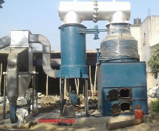
What is Thermic fluid heater?

A thermic fluid heater, also known as a thermal oil heater or hot oil heater, is  used to heat a process fluid to a specific temperature using thermal energy. It operates by circulating a heat transfer fluid, commonly referred to as a thermic fluid or thermal oil, through a closed-loop system.

 What is meant by heat transfer fluid in Thermic fluid heaters?

 A specialized heat transfer fluid, often a mineral-based or synthetic oil, is used as the medium to transfer heat. It has high thermal stability and a high boiling point to ensure efficient heat transfer and safe operation at elevated temperatures.

 What type of combustion chamber is used in Thermic fluid heaters? & how heat generation starts?

 A thermic fluid heater is equipped with a combustion system, which can use various fuels such as natural gas, diesel, heavy oil, coal, or biomass. The fuel is burned in a burner assembly to generate heat.

 How does heat exchanger takes role in Thermic fluid heaters?

 The heat exchanger is the core component of a thermic fluid heater. It consists of a coil or tube bundle immersed in the thermic fluid. The hot combustion gases pass through the coil, transferring their heat to the fluid. This process raises the temperature of the thermic fluid.

The heat generated from the combustion process is transferred to the thermic fluid. The hot flue gases and combustion products flow over the surface of a coil or heat exchanger immersed in the furnace. The coil or heat exchanger is filled with the thermic fluid, which absorbs the heat from the hot gases.

 How does circulation of thermic fluid happens in Thermic fluid heaters?

 The thermic fluid, now heated, circulates through the coil or heat exchanger via a circulation pump. The pump provides the necessary pressure to move the fluid through the system.

 How does heat is being utilized from Thermic fluid?

 The heated thermic fluid carries the absorbed heat to the point of application or process equipment where heat is required. This could be reactors, dryers, presses, or any other heat-consuming equipment.

At the point of application, the thermic fluid transfers its heat to the process equipment or medium, raising its temperature as needed. The thermic fluid's temperature decreases as it gives up its heat energy to the process.

The cooled thermic fluid returns to the heater through a separate return line. In the heater, the thermic fluid is reheated by passing through the heat exchanger or coil, where it once again absorbs heat from the combustion process.

 What is the function of expansion tank in Thermic fluid heaters?

 A thermic fluid heater system typically includes an expansion tank to accommodate the expansion and contraction of the thermic fluid as it is heated and cooled during operation. It helps maintain the desired fluid volume and prevents excessive pressure build-up in the system.

 What is the significance of Control system in Thermic fluid heaters?

 A control system is employed to regulate the heating process, including temperature control, fuel supply, and safety features. It ensures precise temperature control and monitors various parameters to maintain safe and efficient operation.

The temperature of the thermic fluid is controlled and maintained within a desired range using temperature control systems. The system may include temperature sensors, control valves, burner modulation, and circulation pump speed control to regulate the fluid temperature.

 What are the various applications of Thermic fluid heaters?

 Thermic fluid heaters found applications in chemical, pharmaceutical, textile, food processing, and oil and gas.

 What are the main advantages of Thermic fluid heaters?

  • High temperature accuracy,
  • Efficient heat transfer,
  • Versatility in fuel options, and the
  • Ability to provide uniform heating over large areas.

 Read powerplant and calculations

What are the various interlocks used in Boilers??


1.What do you mean by Interlocks?

 Interlocks are the programmed or hardwired control system made to protect the machine or system from damages or disturbances

Interlocks and protections involve sensors, cables, wires, local push buttons, logics, timers, probes etc.

 2.What is the significance of interlocks?

 Significance of interlocks;

  • To protect the system against damages/disturbance
  • To protect the equipment
  • To avoid damages to the man and machine
  • To avoid operation disturbances

 3.What are the various protections used in Boilers?

  • High drum level trip
  • Low drum level trip
  • High main steam pressure trip
  • High positive draught trip
  • High negative draught trip
  • High main steam temperature trip

 4.What are the various interlocks provided for Boiler feed pumps?

 Boiler feed pumps trip on acting following interlocks

  • Low de-aerator level
  • High bearing vibration
  • High bearing temperature
  • High feed water temperature at suction
  • High drum level

 5.Write a brief note on Boiler interlocks

 Read Generator and Turbine inter tripping


Sl No.

Interlock

Significance

1

High drum level-FD fans trip followed by fuel feeding system & ID fans

To avoid carryover of water particles in steam

To avoid thermal shock to super heater coils

2

Low drum level-FD fans trip followed by fuel feeding system & ID fans

To avoid over heating of pressure parts due to lack of water

3

FD fans trip-Fuel feeding system trip

To avoid jamming of fuel feeding system & grate

4

High furnace draught-FD & SA fans trip

To avoid furnace explosion

5

Low furnace draught-ID fans trip

To avoid explosion of ESP & related ducts to vacuum pressure

6

High main steam pressure-Boiler trips (FD & fuel feeding system)

To avoid failure of pressure parts due to high steam pressure

7

High main steam temperature-Boiler trips (FD & fuel feeding system)

To avoid failure of pressure parts due to high steam temperature

8

PA fan trips- Fuel feeding system trips

To avoid jamming of fuel feeding system

9

High main steam pressure-Start up vent CV auto open

To avoid failure of pressure parts due to high steam pressure


For more details, read >>>

Power plant and calculations


Read Practical approach to power plant O&M


Practical Approach to Power Plant Operation and Maintenance

IBR STANDARD INSPECTION PROCEDURES


A-Standard Inspection procedure for Dry & thorough inspection

  • Checking the registration number of the Boilers
  • Carryout thorough inspection of Boiler from both inside and out side
  • Check for defects like corrosion, erosion, bend, bulging, pitting, deformation, thermal expansion etc of pressure parts
  • Check thickness of pressure parts
  • Check the conditions of mountings & fittings
  • Witness non destructive tests if required

B-Standard procedure for ground inspection of pressure parts under erection

  • Verification of documents of pressure parts with relevant certificates
  • Verification of approved drawings
  • Checking pressure parts makers stamp & other identification marks with form no-II
  • Checking of leading dimension of the parts & comparing with approved drawings
  • Checking general condition of the pressure parts like dent marks, pitting, bend etc
  • Checking of fittings & mountings with relevant drawings

C-Standard procedure for material inspection

  • Verification of the approved drawings corresponding to the materials & documents
  • Checking of the pressure parts materials with relevant IBR certificate and  approved drawing.Check name of the material, its specification, heat no, cast no.class, size, identification number & stamping etc
  • Checking of leading dimension of the parts & comparing with approved drawings
  • Checking general condition of the pressure parts like dent marks, pitting, bend etc
  • Selection of samples for physical and chemical analysis/testing

D-Standard Procedure for weld set up inspection

  • Verification of approved drawing
  • Verification of Welder’s certificate
  • Verification of the certificates of welding consumables
  • Verification of the approval of contractor for particular job
  • Verification for the procedure of welding procedure
  • Verification for the site satisfactory  simulation test results
  • Verification of test results of pipe, tube or plates
  • Checking of root gap,weld groove profile and alignment of the pressure parts to be welded as per approved drawing
  • Ensure weld joint area to be welded is free from dust, dirt, oil & grease.And also ensure it is crack free
  • Check weld joint identification number.

E-Standard Procedure for welding joint inspection

  • Visual inspection of general condition of the weld joint like, slag, under cut, finish, surface crack, leg length etc
  • Check alignment of the pressure parts
  • Witnessing Dye penetrant test, magnetic particle inspection test & hardness tests if required
  • Selection of weld joints for NDT test like ultrasonic & radio graphic tests

F-Standard Procedure for Boiler Hydraulic tests

  • Verification of the satisfactory non destructive tests of the welding joints
  • Verification of PMI (Positive Material Identification) report of the weld joints
  • Verification of pressure parts calculation approval
  • Verification of all previous inspection reports and Post weld heat treatment (PWHT) charts
  • Check the calibration reports of pressure gauges using for hydraulic test
  • Witnessing Hydraulic test carried out as per IBR-1950
  • Checking of deflection, distortion and extension of pressure parts during hydraulic test
  • Thorough inspection of pressure parts for any leakages and sweating

G-Standard Procedure for Boiler steam tests

  • Verification of the provisional order of the Boiler
  • Witnessing the steam test carried out as per IBR-1950
  • Check, popping pressure, reset pressure, blow down, accumulation, chattering, lift
  • Checking of the performance of the mountings and fittings


Read more >>>> Power plant and calculations


How do you calculate the efficiency of Economiser in Boiler??


What is the Economiser in power plants?

It’s the heat exchanger used in Boilers to recover the heat from exhaust flue gases.

What are the functions of economisers in Boilers?

Functions of economisers:

It recovers the heat from flue gas leaving the boiler, there by reduces the losses

It helps in raising the feed water temperature, there by reduces the fuel consumption

It increases the Boiler efficiency

It lowers the power plant operation cost

What are the different types of economisers?

Types of economisers

Pressurized economisers

Non pressurized economisers

Steaming type

Non steaming pipe

What do you mean by steaming type economisers?

Economisers where only sensible heat is added to feed water

What do you mean by non-steaming type economisers?

Economisers where sensible heat and part of latent is added to feed water

Efficiency Calculations:

ηEco. = (Economiser outlet feed water temperature Two-Economiser inlet feed water temperature Twi)  X 100 / (Economiser inlet flue gas temperature Tfi- Economiser inlet feed water temperature Twi)


 Read APH efficiency calculation

Example:

Calculate the economiser effectiveness, whose feed water inlet & outlet temperatures are 160 Deg C & 240 Deg C respectively & flue gas inlet & outlet temperatures 390 deg C & 220 deg c respectively.


Solution:


Twi = 160 deg C

Two = 240 deg C

Tfi = 390 deg C

Tfo = 220 deg C

ηEco = (Two-Twi) X 100 / (Tfi-Twi)

ηEco = (240-160 ) X 100 / (390-160)

ηEco= 34%


In an non steaming economiser of efficiency 51%, feed water inlet and outlet temperatures are 105 deg c & 160 deg C respectively, calculate the flue gas temperature entering the economiser

Solution:


Twi = 105 deg C

Two = 160 deg C

Tfi = 370 deg C

Tfo = ? deg C

ηEco= 51%


ηEco = (Two-Twi) X 100 / (Tfi-Twi)

51= (160-105 ) X 100 / (Tfi-105)

Tfi X 51-105 X51 = 5500

Tfi = 212.8 deg C


A economiser inlet feed water & flue gas temperature are 125 deg C and 405 deg C respectively, calculate the feed water leaving the economiser, consider efficiency of economiser 43%

Solution:


Twi = 125 deg C

Two = ? deg C

Tfi = 405 deg C

ηEco= 43%


ηEco = (Two-Twi) X 100 / (Tfi-Twi)

43= (Two-125 ) X 100 / (405-125)

12040 = 100 X Two-12500

Two = 245.4 deg C


For more calculations related to power plant read Powerplant & Calculations


Reasons for Priming, Foaming and carryover in Boilers


Priming:

1. What do you mean by the term Priming?

Priming means carryover of water particle in the steam

2. What are the reasons for Priming?

Reasons for priming;

  • Improper design of Boiler and steam drum
  • Maintaining high drum level
  • Boiler load fluctuation
  • Sudden load raise due to steam demand
  • Foaming in feed water
  • Miss operation of Boiler
  • Sudden lifting of Boiler safety valve or start up vent CV
  • More impurities in Boiler water

3. What are the impacts of Priming?

Impacts of Priming;

  • Lower steam efficiency
  • Water hammering
  • Super heater coil failure due to thermal shock
  • Turbine high vibration & blade failure

How do you avoid priming in Boilers?

Priming can be avoided by;

  • Proper operation of boiler
  • Maintaining drum level in between 45 to 55%
  • Avoiding foaming
  • Avoiding sudden load fluctuation
  • Proper designing of Boiler

Carryover:

What do you mean by the term carryover?

Carryover is the carryover of solid, liquid & gaseous contaminants with water and steam leaving the drum due to incomplete separation of water and steam in steam drum.

What are the major reasons for carryover?

Reasons for carryover;

  • Defects in steam and water separators
  • Foaming
  • Boiler load fluctuation
  • Higher drum level
  • Boiler steam drum construction defects

What are the effects of carryover on Boiler components?

Contamination in steam leads to deposition of solid scale on Super heater coils & control and regulating valves.

Foaming:

What do you mean by the term foaming?

Foaming is the formation of unbroken bubbles on the surface of the boiler water inside the boiler drum.

The bubbles may be in thin layer with few bubbles overlying each other or it may build up throughout the steam space.

What are the reasons for foaming?

  •  High suspended solid concentration
  •  High alkalinity concentration
  •  High dissolved solid concentrations in the boiler water
  •  Oil and organic contaminants in the boiler water
  • High impurities
  • High dosage of chemicals
  • High water level

How do you avoid foaming?

  • Timely blow down & maintaining desired water quality
  • Maintaining constant load on Boiler
  • Avoiding high water level
For more articles read Power plant and calculations

Combustion air in Boilers and related calculations

1. What do you mean by combustion air?

The amount of air required for complete combustion of fuel in furnace is called as combustion air. The efficiency of the Boiler or furnace depends on efficiency of combustion system.

2. On what parameters the requirement of combustion air depends?

Combustion air requirement depends on;

  • Type of fuel burnt
  • Type & quantity of its elemental constituents
  • Type of Boiler and furnace
  • Amount of moisture content in it

3. What is the relation between moisture content in the fuel & combustion air required?

Combustion air requirement increases as the moisture content in the fuel increases and vice versa

4. What is the relation between carbon & Hydrogen content in the fuel & combustion air required?

Combustion air requirement increases as the % of carbon & Hydrogen content in the fuel increase and vice versa.

5. What is the relation between oxygen content in the fuel & combustion air required?

Combustion air requirement decreases as the % of oxygen content in the fuel increases and vice versa.

6. Do content of sulphur & Nitrogen in the fuel affect combustion air requirement?

Increase and decrease in sulphur & Nitrogen content in the fuel does not affect much on combustion air requirement.

7. What is meant by total air of combustion?

The total air supplied to the Boiler combustion chamber is divided into two parts Primary air and secondary air.

Primary air supports the flame and takes part in the initial combustion process. The second part is called as secondary air. Secondary air is admitted into the furnace from top to create turbulence in furnace and to ensure complete combustion of the fuel.

8. What are the functions of Primary and secondary air in Travelling grate, pulverized coal fired and FBC Boilers?

In case of travelling grate Boilers Primary air is supplied below the grate to support flame & combustion stabilisation. And secondary air from top of the furnace as over fired air to create turbulence for complete combustion. And also secondary air is used to spread the fuel in furnace

In case of Pulverized coal fired Boilers, Primary air is used to carry the pulverized coal into the furnace.

In case of FBC Boilers Primary air is used to carry fuel and fluidisation. Secondary air is supplied above the bed to ensure complete combustion

9-What is meant by theoretical air & excess air in combustion?

Theoretical air: Amount of air required to burn the fuel. It is stoichiometric air, it does not ensure complete combustion.

Excess air: Amount of extra air given for complete combustion

10-Calculate the Theoretical air required to burn imported coal having carbon 55%, Oxygen 8.2%, Hydrogen 3.3% and sulphur 0.32% in it

Theoretical air is calculated by using below formula

Thair = (11.6 X %C + 34.8 X (%H2-%O2/8) + 4.35 X %S)) / 100

Thair = (11.6 X 55 + 34.8 X (3.3-8.2/8) + 4.35 X 0.32)) / 100

Thair = 7.18 kg/kg of fuel burnt

In the above formula, you can vary the % of Carbon, Hydrogen & Sulphur to observe changes in air requirement

11-How do you measure % of excess air supplied?

Excess air is generally measured from Oxygen analyser installed at the out let of Boiler (Economiser)

It is to be noted that, excess air & excess oxygen are not same. Air has around 21% of oxygen in it by volume. So, 100% excess air is roughly equals to 10.5% of oxygen.

12-What is the significance of excess air?

For combustion, if less air is supplied it leads to incomplete combustion forming CO instead of Co2. And if more excess air is supplied it leads to reduction of combustion efficiency by cooling the furnace & carrying the heat through flue gas.

So, it is important to adjust the air supply in such a way that complete combustion will take place without much extra air.

13-Calculate the % of excess air required if oxygen measured in flue gas at economiser outlet is 5.5%.

Excess air = O2% X 100 / (21-O2%)

Eair = 5.5 X 100 / (21-5.5)

Eair = 35.48%

14-Calculate the total air required for complete combustion of coal if Theoretical air supplied is 7.1 kg/kg of coal and O2 measured in flue gas is 6.4%

Actual or total mass of air supplied = (1 + Excess air / 100) X theoretical air

We have

Excess air = O2% X 100 / (21-O2%)

Eair = 6.4 X 100 / (21-6.4)

Eair = 43.84%

Actual or total mass of air supplied = (1 + 43.84 / 100) X 7.1

Actual or total mass of air supplied = 10.21 kg/kg of coal

15-How do you control the excess air?

Excess air is controlled by;

  • Optimizing the moisture content in the fuel
  • Improving combustion chamber performance
  • Auto control of fuel feeding
  • Continuously monitoring O2 content in flue gas
  • Incorporating auto combustion control
  • Incorporating VFD drives to ID, FD, PA & SA fans

16-Among Bagasse, coal and Natural gas, which fuel needs more excess air?

Bagasse, since it has more moisture content

17-A boiler has supplied 27% excess air, calculate % of O2 in flue gas

Excess air = O2% X 100 / (21-O2%)

27 = O2% X 100 / (21-O2%)

27 X 21 -27 X %O2 = 100 X O2%

567= 127 O2%

O2% = 4.46

Read Powerplant & calculations


Reasons for priming, foaming and carryover in Boilers

Slop fired Boiler start up procedure


Pre-checks

  • Ensure DM water storage tank, feed tank & Deaerator  level are normal
  • Ensure availability of start up fuel (wood) & main fuel (coal) and power supply with DG backup
  • Ensure maintenance & trial runs (healthiness) of all equipment including fuel handling, ash handling / auxiliaries, motorized valves, actuators, control valves and PRDS controls are completed successfully
  • Ensure that all interlocks / protection and controls are checked & taken in line.
  • Ensure expansion pointers are cleaned & tramps are in good condition.
  • Ensure Boiler manholes and flue gas path system manholes are boxed up.
  • Ensure availability of chemical dosing system and readiness of drum level gauge glass with illuminator assembly.
  • Ensure availability of cooling water, instrument air and service air.
  • Ensure Coal bunker is filled with required level
  • Ensure all rotary air lock valves of evaporator, economizer & bag filters are open
  • Ensure healthiness of all dampers and keep them in open/close marked positions as per requirement
  • Open all air releases/vent valves in boiler drum and open super heater header drains and its vent valves.
  • Ensure all boiler bottom ring header drains, blow down valves and main steam stop valves including its bypass valves are closed.
  • Ensure Boiler feed pump’s bearings oil level normal, minimum recirculation, balancing leak off valves & suction valves are open, cooling water pressure normal.

Boiler start up

  • Start the ACW pump, Instrument Air & Service Air Compressor
  • Start BFP from control room. Ensure suction pressure, balancing pressure & discharge pressure normal. Bearing temperature & Vibrations normal. Ensure motor draws current normal & sound normal. Shut the BFP immediately if any abnormal condition and check thoroughly before restart.
  • Start water filling the boiler drum through 30 % control valve and maintain the drum level up to 30%.
  • Start the Ash handling plant prior to light up the Boiler. Then start all hoppers RAV.
  • Ensure bag filter main damper is closed & bypass damper is open
  • Maintain the drum level about 40%.
  • Drum vent, super heater vent and main steam line drain should be kept open.
  • Start wood firing by spraying small quantity of diesel & slowly raise the furnace temperature
  • At furnace temperature > 150 deg C start ID & FD fans at minimum speed
  • Close drum air vent at 2.5 kg/cm2
  • At 3 kg/cm2, gibe blow down to CBD, IBD & bottom headers one by one for 30 sec to 45 seconds
  • At pressure > 4 kg/cm2, open start up vent 10% initially & close the top header drain valves & go on increasing the pressure
  • At furnace temperature around 250 deg C, start coal feeding by starting SA fan
  • Now slowly increase fuel feeding & FD air
  • When boiler pressure reaches 6 kg/cm2 & 150 deg C, charge the main steam line. Before charging the main steam line, open all the drains at 100 % and warm up vents at minimum opening and then open the MSSV bypass valve.
  • Start HP & LP dosing and maintain recommended drum water parameters of boiler. Keep the CBD at minimum opening to maintain recommended residual PO4 & conductivity of drum water
  • Check & record thermal expansion of boiler pressure parts and record the bearings temperature & vibrations of auxiliary equipment’s associated with Boiler
  • After ensured all condensate removed & color less steam comes through drains, keep all the drains in crack position, then open main steam stop valve and close the bypass steam valve
  • At Boiler pressure 9 kg/cm2 & temperature 180 deg C, charge Deaerator & SCAPH through PRDSH
  • At flue gas temperature > 180 deg C take bag filter into line
  • Observe seal air pressure, conveying air vessel pressure of AHP is normal.

Slop firing:

  • Ensure sufficient quantity of slop with required brix is available in slop tank
  • Ensure tank coil heater & steam tracing lines are charged & tank slop temperature is 70 to 80 deg C
  • Ensure slop pumps are healthy & agitator is running condition
  • After ensuring above all are normal, start slop transfer pumps & keep slop in recirculation mode for at least 2 to 3 hours before taking into boiler
  • As the Boiler reaches 50 to 60% of MCR & furnace temperature is 450 to 500 deg C open the atomizing steam line, slowly introduce the slop into furnace by opening SOV
  • Note: Before introducing slop into nozzle, keep open the steam connection line provided with respective nozzle.
  • Quantity of slop fired at MCR is 3.91 TPH & slop quantity should be reduced as the load demand reduces
  • Always maintain 20 to 25% supporting fuel on heat basis. Never start the Boiler with slop
  • During slop firing ensure supplement fuel is supplying continuously to avoid clinker
  • The soot blowers provided in economizer, evaporators are operated once in a shift & wall blowers twice in a shift

 Read more on Power plant & Calculations>>>>>


15-Emergencies in power plant operation

Most visited posts