Slop fired Boiler start up procedure


Pre-checks

  • Ensure DM water storage tank, feed tank & Deaerator  level are normal
  • Ensure availability of start up fuel (wood) & main fuel (coal) and power supply with DG backup
  • Ensure maintenance & trial runs (healthiness) of all equipment including fuel handling, ash handling / auxiliaries, motorized valves, actuators, control valves and PRDS controls are completed successfully
  • Ensure that all interlocks / protection and controls are checked & taken in line.
  • Ensure expansion pointers are cleaned & tramps are in good condition.
  • Ensure Boiler manholes and flue gas path system manholes are boxed up.
  • Ensure availability of chemical dosing system and readiness of drum level gauge glass with illuminator assembly.
  • Ensure availability of cooling water, instrument air and service air.
  • Ensure Coal bunker is filled with required level
  • Ensure all rotary air lock valves of evaporator, economizer & bag filters are open
  • Ensure healthiness of all dampers and keep them in open/close marked positions as per requirement
  • Open all air releases/vent valves in boiler drum and open super heater header drains and its vent valves.
  • Ensure all boiler bottom ring header drains, blow down valves and main steam stop valves including its bypass valves are closed.
  • Ensure Boiler feed pump’s bearings oil level normal, minimum recirculation, balancing leak off valves & suction valves are open, cooling water pressure normal.

Boiler start up

  • Start the ACW pump, Instrument Air & Service Air Compressor
  • Start BFP from control room. Ensure suction pressure, balancing pressure & discharge pressure normal. Bearing temperature & Vibrations normal. Ensure motor draws current normal & sound normal. Shut the BFP immediately if any abnormal condition and check thoroughly before restart.
  • Start water filling the boiler drum through 30 % control valve and maintain the drum level up to 30%.
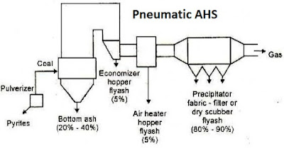
  • Start the Ash handling plant prior to light up the Boiler. Then start all hoppers RAV.
  • Ensure bag filter main damper is closed & bypass damper is open
  • Maintain the drum level about 40%.
  • Drum vent, super heater vent and main steam line drain should be kept open.
  • Start wood firing by spraying small quantity of diesel & slowly raise the furnace temperature
  • At furnace temperature > 150 deg C start ID & FD fans at minimum speed
  • Close drum air vent at 2.5 kg/cm2
  • At 3 kg/cm2, gibe blow down to CBD, IBD & bottom headers one by one for 30 sec to 45 seconds
  • At pressure > 4 kg/cm2, open start up vent 10% initially & close the top header drain valves & go on increasing the pressure
  • At furnace temperature around 250 deg C, start coal feeding by starting SA fan
  • Now slowly increase fuel feeding & FD air
  • When boiler pressure reaches 6 kg/cm2 & 150 deg C, charge the main steam line. Before charging the main steam line, open all the drains at 100 % and warm up vents at minimum opening and then open the MSSV bypass valve.
  • Start HP & LP dosing and maintain recommended drum water parameters of boiler. Keep the CBD at minimum opening to maintain recommended residual PO4 & conductivity of drum water
  • Check & record thermal expansion of boiler pressure parts and record the bearings temperature & vibrations of auxiliary equipment’s associated with Boiler
  • After ensured all condensate removed & color less steam comes through drains, keep all the drains in crack position, then open main steam stop valve and close the bypass steam valve
  • At Boiler pressure 9 kg/cm2 & temperature 180 deg C, charge Deaerator & SCAPH through PRDSH
  • At flue gas temperature > 180 deg C take bag filter into line
  • Observe seal air pressure, conveying air vessel pressure of AHP is normal.

Slop firing:

  • Ensure sufficient quantity of slop with required brix is available in slop tank
  • Ensure tank coil heater & steam tracing lines are charged & tank slop temperature is 70 to 80 deg C
  • Ensure slop pumps are healthy & agitator is running condition
  • After ensuring above all are normal, start slop transfer pumps & keep slop in recirculation mode for at least 2 to 3 hours before taking into boiler
  • As the Boiler reaches 50 to 60% of MCR & furnace temperature is 450 to 500 deg C open the atomizing steam line, slowly introduce the slop into furnace by opening SOV
  • Note: Before introducing slop into nozzle, keep open the steam connection line provided with respective nozzle.
  • Quantity of slop fired at MCR is 3.91 TPH & slop quantity should be reduced as the load demand reduces
  • Always maintain 20 to 25% supporting fuel on heat basis. Never start the Boiler with slop
  • During slop firing ensure supplement fuel is supplying continuously to avoid clinker
  • The soot blowers provided in economizer, evaporators are operated once in a shift & wall blowers twice in a shift

 Read more on Power plant & Calculations>>>>>


Turbine lube oil flushing procedure


Oil pipe lines cleaning & flushing:

Generally Steam Turbo Get machineries lube oil supply line & control oil lines are of stain less steel & return oil lines are of carbon steels. The oil pipelines fabricated at site are to be cleaned by acid pickling for CS pipelines and by Caustic Soda for SS pipelines.

Before acid pickling the pipes should be thoroughly flushed with air for removing of loose particles.

Acid pickling pipes should be dummied one end with rubber gasket and filled with acid of 5 to 8% of concentrated HCL acid and keep the pipes filled with acid for 24 hours, so that all loos metal particles will come out. There after remove the acid from pipes & clean the pipes thoroughly with water and neutralize with caustic soda.

Fill the 3 to 4% of concentrated caustic soda solution in the acid cleaned pipelines and keep the pipes for 24 hours, so that all acid contents gets neutralized.

Ensure the time between acid cleaning and soda wash should be kept minimal Also chemical solution should not exceed 60˚C. After that all soda washed pipes are thoroughly cleaned/rinsed with water and dry with Air, Lube oil (ISO VG 46) to be applied inside the pipelines to avoid rusting.

All the passivated pipelines are covered both the ends of pipes with plastics caps / lids so that no dust particles can enter inside. All passivated pipelines are to be fitted immediately in the original position and start the oil circulation / flushing.

Reference books for power plant O&M

Turbine oil flushing:

Pre-checks or requirements for oil flushing;

  • Fire fighting system at MOT and STG area is ready to use.
  • Main oil tank should clean thoroughly using sponge/Cloth, diesel and with compressed air
  • Ensure AOP suction strainers are cleaned and boxed up properly
  • Fill the Oil Tank with flushing oil of Grade ISO VG 46 (refer O&M Manual) through centrifuge by site suitable temporary flexible hose connection. Temporary hose connection one end is immersed in the oil barrel and another end is connected to oil centrifuge inlet point. Centrifuged oil should be send from oil centrifuge outlet to Main oil tank by permanent piping. Flushing oil should be same as per first fill oil. The detailed specification & makes are specified in the operation & Maintenance manual
  • Ensure Main oil tank level should be > 65% or as per requirement in local level gauge
  • Before start up the LOS system please ensures there is no bypass in protections of motors like-Over load, single phase preventer etc.
  • All the Oil Pumps & Main oil tank fans are kept ready for operation. Ensure Emergency local Buttons of all the motors are released condition.
  • MOT heaters should on. Also ensure Heaters to be cut of at 65 ˚C of MOT Oil temperature
  • Ensure MOT Mist fans power supply panel are in charged condition and Mist fan kept ready to start
  • Ensure Aux. Oil pump power supply panel is in charged condition kept ready to start.
  • Ensure STG Barring gear motor, EOP motor & ACOP motors power supply is switched off condition.
  • Ensure AOP pump suction and discharge Pressure Gauges are working and its isolation valves are in opened condition.
  • Ensure any one of the Lube oil cooler is line up i.e the inlet 3 way valves is directed in one cooler only and cooler equalizing valve is in closed position. Also ensure corresponding lube oil cooler vents and drains are in closed condition
  • Lube oil cooler inlet and outlet cooling water valves are in closed condition. Ensure cooling water to be charged up to isolation valves during flushing
  • Ensure lube oil cooler inlet Pressure Gauge isolation valves are open. Also ensure All PTs (if applicable) isolation valve is closed condition during flushing to avoid entry of any foreign particles.
  • Remove the original filter elements (625 mesh) from filters skid & put Temporary made filters element (perforated pipe and rolled with temporary filter screen having sizes start from 50 mesh and fastened by wire) to both filter shell.
  • Ensure any one of the Lube oil filter is line up i.e. inlet 3 way valves are directed in single oil filter only and equalizing valve is in closed condition. Ensure Lube oil temporary filters are cleaned and box up properly. Ensure Lube Oil filter drains and vents are in closed condition. Ensure Lube Oil filter line inlet & outlet Pressure Gauges is working and its isolation valves are open.
  • Ensure Lube oil header Pressure Gauge is working and its isolation valve is open and PT‟s isolation valves are closed condition during flushing to avoid entry of any foreign particles.
  • Turbine front & Rear bearing pedestal flanges oil inlet to out let, Gear box flanges oil inlet to out let, Alternator Front & Rear bearing pedestal flanges oil inlet to out let should be bypassed during oil flushing by suitable temporary hose pipes.

Procedure:

Stage-1

  • Start AOP & check any oil leakage from the pipe lines welding joints & flange joints
  • Observe lube oil header pressure rising
  • Monitor the lube oil circulating through bearings bypass hose pipes
  • Observe AOP oil pressure regularly, if discharge pressure is decreasing it means that, pump’s suction strainer is jammed. So stop the pump, clean the strainer & again restart the AOP
  • Observe the Lube oil filter DPs if it crosses 0.6 kg/c2 change over the filter to stand by filter
  • Raise the lube oil temperature 55 to 65 ˚C by MOT heaters or Temporary heaters. Once the oil temperature raised 55 to 65 ˚C lightly hammer the line with mallet or soft hammer so that all the loose materials will come out with the oil.
  • After duration of two to three hours, change over the filter to the stand by one and check for the cleanliness of the mesh and if required replace the same. These processes are to be repeated by changing the filters in line and also mesh if required at intervals of 2hrs, 4hrs, 8hrs durations..
  • Every 4 hours reduce the oil temperature by raking lube oil cooler into line. This thermal shock will helpful for expansion & contraction of pipe lines thereby removing scale & clogged particles inside the pipe lines & other system.
  • Once 50mesh cleared then change to 100mesh then 150mesh and then 200mesh.This process to be continued up to 200mesh cleanness. Once 200 meshes are cleared then follow the Stage -2 flushing.

Stage-2

  • Remove top half of the bearings (Thrust, Front & Rear) of T u r b i n e Rotor and keep them at safe location-Clean the preservatives which applied in the rotor. Re-place the bearing caps and their housing/cover in its position and ensure that oil will not spill out during flushing.
  • Turbine front and rear pedestal loop line (flexible hoses) to be removed and normalized the inlet and out let connections as per original. Ensure Loop will be continued in the gearbox & Alternator bearings which are bypassed with flexible hoses.
  • Ensure the temporary made filters element filter screen having sizes start from 50 mesh.
  • Repeat the procedure as per Oil flushing Stage -1 Continue flushing further till system is clear. Once 200 meshes are cleared Oil flushing is completed.

Stage-3

  • Completely drain the oil from MOT, coolers, filters and piping system.
  • Once the MOT is drained completely, open oil tank cleaning, Clean the tank internals using site suitable special wipers with long rod along with compressed air. After cleaning, fill fresh lube oil inside the tank, ensure that oil is sprayed throughout inside of the tank (Sprayer-site suitable hose connection). Once the oil fogging is over fix the oil cleaning door with oil gasket and apply the grease on the gasket before tightening the bolts.
  • Remove the Turbine thrust, front & rear bottom half the bearings from respective pedestals by small amount of lifting the Turbine rotor (max 0.1mm only)
  • Remove the Turbine thrust, front & rear bottom half the bearings from respective pedestals by small amount of lifting the Turbine rotor (max 0.1mm only)
  • Completely disassemble and clean the Turbine thrust, front & rear bearings by petrol or site suitable cleaning medium. All bearings pads to be inspect. Clean/polish both top & bottom halves. Ensure their correct fitting. Clean the holes provided in Thrust Bearings Pads holder & Journal Bearing holes also
  • Insert the Turbine thrust; front & rear bottom half of the bearings in the respective places. Rest the Turbine rotor on the bearings
  • Assemble thrust, front & rear top half of the bearings in the respective places. Ensure required clearances as O&M Manual recommendations
  • Position the bearing caps/cover and tightens the cap studs as per torque recommended
  • Ensure all pumps (AOP, MOP, EOP & ACOPs) suction strainers are well cleaned and boxed up properly
  • Ensure both filters skid temporary filters are removed and filter skid is thoroughly cleaned. Insert the original filters in the respective places.
  • Main oil tank – Oil should be filled through centrifuge with first fill oil of OEM recommended Grade 

Do not use: Flushing oil for final filling of MOT, if required get it tested from authorized party or OEM.

  • Ensure Loop lines (flexible hoses) to be removed in the gearbox & Alternator bearings and normalized the inlet and out let connections as per original
  • Ensure all dummies are removed which installed in PRVs, MOP & EOP discharge piping, control oil line and trip oil line system.
  • Ensure all field instruments are fitted properly & they are taken into line
  • Take All PRV’s into line
  • Ensure all flange joints are fitted correctly
  • Ensure all interlocks are in line
  • Start the AOP & circulate the lube oil throughout the system


 For such more articles READ

POWER PLANT & CALCULATIONS


 Why do turbines go into over speed trip???


 Read Power plant O&M book...Practical approach to power plant O&M


Slop fired Boiler bag filter commissioning & shutdown procedure


Pre-Coating & Pre-heating

  • Box – up the bag house and close all access doors properly.
  • Keep the module outlet damper full open.
  • Close the Bypass dampers 100%.
  • Close the inlet damper 100%.
  • Make sure that the lime injection system is ready
  • Run the ID Fan and adjust the fan controls for effective suction for pre coating. (the air will flow from the boiler section .If required doors in the economizer section can be opened to draw fresh air into the bag filter)
  • Run the ID Fan and adjust the fan controls for effective suction for pre coating. (the air will flow from the boiler section .If required doors in the economizer section can be opened to draw fresh air into the bag filter)
  • Switch ON the lime injection system and start lime spray into the inlet duct. (Note : Dolomite powder can be used for pre coating)
  • Do not start pulsing during this period.
  • Observe the change in Differential pressure across the tube sheet.
  • After sufficient pre coating, as observed from the Diff Pressure gauge, around 10-  15 mmWG increases, stop the pre coating. Record the readings.
  • Stop the ID fan.
  • Switch on the hopper heaters
  • Switch on the Close Circuit heating system as follows
  • Close the bag filter inlet & outlet dampers.
  • Open the heating system inlet and outlet valves.
  • Start the blower.
  • Switch on the heaters.
  • Allow the hot air circulation to push up the internal temp > 140 Deg C (Approx).

Bag filter start up

  • Open the Bypass dampers both multi lower and puppet dampers by 100%
  • Keep Bag filter inlet and outlet dampers closed.
  • Ensure that the operation of dust conveying system below the hoppers is checked thoroughly and should be kept in operation
  • Light up the boiler and take the exhaust gases through the bypass path.
  • Continue with only coal firing.
  • Once the gas temperature reaches 140 Deg C +, then take the bag filter in line
  • Keep the BF pulsing OFF from the beginning
  • Open the bag filter inlet and outlet dampers 100%
  • Start closing the multi lower damper in the bypass line gradually, by maintaining the furnace pressure. This will divert the gas gradually through the bag filter. The ID fan speed will go up gradually. This process will take some time
  • When the entire gas is diverted through the bag filter and the multi lower damper in the bypass line is fully closed, and then close the puppet damper in the bypass line fully. (Caution: If the bypass dampers is not fully closed then the dust gases can escape to the stack through this route and push up the emission level).
  • Continue Coal firing and allow Bag filter inlet temperature to cross 180 Deg C.
  • Put the Bag pulsing in demand cleaning mode – Cleaning to start at 175 mmWG and stop at 150 mmWG. This can be readjusted if required.
  • Adjust the pulse air pressure to 3.5 Kg/Cm2.
  • Adjust Sol. Valve ON time 100 msec , OFF time 25 Sec (to start with)
  • Start spent wash firing and increase it gradually in small steps. (Caution: Sudden increase in spent wash firing rate can lead to clinker formation in boiler and chocking of bags in the filter.)
  • Start the lime injection system ( Quantity : Lime powder with 50 to 150 microns mesh size @ 150 kg/Hr)
  • Restrict the bag filter inlet temp between 180 – 220 Deg C (Max 240 DegC for ½ Hr).
  • Record all readings every one hour as given in the log sheet.

Bag filter shut down

Slop fired boiler start up procedure

  • After shutdown or tripping the boiler follow following procedures to shutdown bag filter
  • Start opening the puppet


    damper fully, after full opening of puppet damper, slowly start opening regulating damper adjusting the furnace pressure & ensure full opening of the damper.
  • Close inlet and outlet dampers of the bag filter.
  • Keep the pulsing on through timer mode for around ½ hr to dislodge the dust from the bags when the inside temp is high (Caution: Do not pulse the bags when the inside temp is low this may clog the bags.
  • Keep the hoper heaters ON.
  • Open the inlet and outlet valves of the heating system.
  • Start the heating system fan & heater to keep the internal temp to above 140Deg C for ½ hr, till the bag pulsing is over. Keep the dust conveying system ON for at least 1 hr to remove all the dust from the hopper.
  • After ½ hour a) Stop the bag pulsing b) Stop the close Circuit heating system. c) Stop the hopper heating system
  • Allow the bag filter to cool down in boxed up condition before opening the access doors. Then open the access doors and allow the natural purging before entering inside the filter. 

Questions & Answers on Ash handling system

1.What is Ash?

Ash is the remaining product of solid or liquid fuel after burning

2.What are the various components of Ash?

Ash has following components

  • Silica (SiO2)
  • Alumina (AlO3)
  • Iron Oxide (Fe2O3)
  • Sodium Oxide (Na2O)
  • Potassium Oxide (K2O)
  • Calcium Oxide (CaO2)
  • Magnesia (MgO)

3.Which fuel has more ash Liquid, solid or Gaseous fuel?

Solid, Liquid & Gaseous fuels are having more ash consecutively

4.What are the various types of ash produced in Boilers?

Bottom ash & Fly ash are generated in Boilers

5.Which ash is more in quantity?

Generally Fly ash is more around 70-80% & bottom ash is around 20-30%

6.What do you mean by Fly ash?

Ash which is carried out by flue gas is called fly ash.

7.What can fly ash could cause in downstream system of The Boiler?

  • If ash is more, it creates following problems in downstream of the Boiler
  • Improper heat transfer in Super heaters, economizers & APH
  • Erosion of pressure parts & flue gas ducts
  • If there is low velocity, ash deposits in ducts, APH ESP etc

8.Which type of Ash removal is more dangerous & why?

  • Bottom ash removal is more dangerous, because;
  • Bottom Ash is at higher temperature
  • Ash is high Abrasive & Corrosive in Nature
  • When it comes in contact with water high hot fumes are formed
  • Risk of frequent clinker formation

9.What are the different devices or systems used to separate Fly ash from flue gas before letting it into atmosphere?

  • Electrostatic Precipitator
  • Bag filter (Fabric separators)
  • Wet scrubber
  • Inertial separators (Settling chamber, Baffle chambers, Cyclone separator)
  • Fabric hybrid filter

10.Briefly explain the Fabric Separator type bag filters

In this system, fabric bags are used to filter the flue gas to separate the dust. Dust laden gases enter the bag house and passes through fabric bags which act as filter.The bags are woven with material nylon, fiber glass etc. Each bag is externally supported by steel/metal cage. The bag filter house is provided with an explosion vent to avoid explosion during abnormal operation conditions.

Further, the bag filter house consists of hoppers & ash handling system to remove fly ash separated in bag filters.

In bag filters, the dust collects at the outer surface of the bag since flue gas flow from out side to inside of the bag.

Mechanism of dust collection:

Gravity: Due to gravitational force & sudden lower velocity large sized dust/ash particles fall down into hopper due to Gravitational force.

Inertial collection: Due to inertial, heavy dust particles strike the bag filters placed in the flue gas path & fall down into the hopper, since they do not change their flow direction due to inertia.

Interception: Due to the fine mesh or size of the bag filters, dust or ash particles cannot cross the filters. Instead they hit filters & fall down into the hopper.

Electrostatic effect: Electrostatic force between dust particles & bag filter causes the dust to capture.

11.How do you remove dust particles from Bag filters?

  • Mechanical Shaker
  • Reverse air
  • Reverse Jet

12.What are the various materials of composition (MOC) of Bag filters?

Sl No.

Bag filter material

Operating temperature (0C)

1

Nylon

85-90

2

Polyester

130-140

3

Polyphenylene  sulphide or Ryton

180-190

4

Fibre glass

250-260

5

Fibre glass fabric coated with PTFE

250-260

13.What are the various factors considered for selection of Bag filters?

  • Flue gas temperature
  • Moisture level in flue gas
  • Dust or ash particles size
  • O2% in flue gas
  • Flue gas velocity
  • Dust or ash particles abrasiveness
  • Air to cloth ratio

14.What are the main functions of Ash handling system?

  • To remove the ash from Boiler furnace & other various ash discharge points
  • To convey this ash to nearby storage area like ash silo
  • Ash disposing

15.What are the various types of Ash handling systems used in Boilers?

Mechanical ash handling system: In this system chain, belt & screw conveyors are used to convey the ash from various ash termination points to ash silo.


Pneumatic ash handling system:


Pneumatic ash handling system is used widely in most of the Power plants. High pressure air is used to convey the ash to the suitable location.

16.What are the various types of Pneumatic ash handling systems used in Boilers/power plants?

  • Lean phase ash handling system
  • Medium phase
  • Dense phase

17.Why dense phase ash handling system is used in almost all Boilers Ash handling plant?

Because it has less air consumption due to volumetric ration of air & ash is more. Sometimes instead of pressurized air vacuum system is used to convey the ash.

Briefly explain the dense phase Ash handling system

In this system, Ash conveying system is placed just below the ash hopper. This system consists of Main ash hopper

  • Surge hopper with electromagnetic or Mechanical vibrators
  • Knife edge gate valve
  • SS expansion bellow
  • Dome valve assembly & operating mechanism
  • Ash & air conveying valves, solenoid valves
  • Pressure switches & limit switches
  • Conveying pipelines

If the temperature of the ash is more (Economiser & APH) surge hopper is made with water jacket for continuous circulation of water.

The system can be operated from local & remote in probe mode or timer mode.

Calculation part:

1. A Boiler is consuming 72 TPH an imported coal having ash % 8, calculate the total ash generated in a complete month. Assume there is no stoppages or load fluctuation

Total coal consumed in a month = 72 X 24 X 30 = 51840 MT

Total ash generated in a month = 51840 X 8 / 100 = 4147.2 MT

2. A boiler consumes 7 TPH of coal, calculate the total fly ash generated in a day if coal has 35% ash.

Total ash generated = 7 X 24 X 35 / 100 = 58.8 MT

We know that, fly ash is around 80% of total ash.

So total fly ash generated is 58.8 X 80 / 100 = 47.04 MT

3. A Boiler generates 20 MT of ash in a day, calculate total coal consumed in a day if coal has 5% of ash in it

Total ash generated =20 MT/day

Ash % in coal = 5%

Therefore total coal consumed = 20  / 5% = 400 MT


 For related articles read Power plant & Calculations


boAt Rockerz 255 Pro+ Bluetooth Wireless in Ear Earphones with Mic (Teal Green)


Questions & Answers on steam Blowing


1.What is the purpose of steam blowing?

The purpose of the steam blowing is to remove any foreign materials from steam piping & super heater coils after completion of erection work.

2.What will happen if steam blowing is not done after erection or repair of Boiler?

If steam blowing is not done, considerable damage will happen to the steam lines & other end user applications like steam turbine, process heat exchangers due to scale, debris & other foreign materials present in the newly erected pipe lines/coils.

3.What is the basis behind steam blowing?

The basis behind the steam blowing is to create momentum equal to or preferably greater than that during normal operation. This will blow out all the debris from the steam lines

4.What are the two different methods of steam blowing?

Puff method & continuous method. In puff method thermal shock is created & in continuous steam blowing, constant steam purge is maintained

5.What are the requirements for steam blowing for newly erected Boilers?

  1. Steam blowing area is corned off & notice board or caution board should be displayed
  2. Ensure Boiler hydraulic test, alkali boil out & passivation procedures are completed before steam blowing
  3. All the temporary supports used during erection should be removed
  4. Steam pipe lines & valves used for steam blowing line should be equal to the maximum size of permanent pipe.
  5. Sharp elbows, bends & tees should be avoided in steam blowing pipe line to avoid more pressure drop
  6. Temporary pipe lines used for blowing should be well supported to withstand reaction forces created during steam blowing.
  7. Steam blowing line should be terminated outside the Turbine hall or process
  8. Sufficient allowance should be given to steam blowing line for thermal expansion
  9. Ensure steam line supports & hangers are erected & set properly
  10. Ensure control valves, steam nozzles & NRV flops are not installed during steam blowing
  11. Initially steam blowing is done at lower mass flow

6.What is the time gap between two steam blows?

For an un insulated steam pipe line blowing can be done at every 1 hr. And for insulated steam pile line the gap between two blows should be 3–4 hours

7.Which materials are used for target plates?

Aluminum & stain less steel

8.How do you decide the steam is clear after blowing?

 If there are only two or less than two recognizable impressions found on per square centimeter of target plate, then the target plate is said to be clean.

For Target Plate Made of Aluminum:

The piping considered clean if there are not more than 3 (Three) pitting of 0.5 mm to 1mm dia. in center area of 25 mm X 25 mm and shall not have any deformed edges. Besides this there shall be no pitting in the rim zone. Pitting below 0.5 mm may be ignored.

For Target Plate Made of Stainless Steel:

 The piping is considered clean if there are not more than five pitting of 0.1 mm dia to 0.5 mm dia. in center area of 50 mm X 50 mm & shall not have any deformed edges. Pitting below 0.1 mm may be ignored 

Read reference books for power plant O&M

For more related articles on power plant

Read

Power plant & Calculations

Standard operating procedure of CHP & Dust extraction system


SOP FOR CHP START UP


  • Ensure trained CHP operator & helper are available
  • Ensure adequate illumination is available
  • Ensure Operator has walky-talky for proper communication with control room
  • Have field round on entire CHP & ensure all conveyors are empty & no any foreign materials on belt.
  • Ensure no any maintenance or inspections are going on by other department
  • Ensure all interlocks & local hooters are healthy
  • Ensure shuttle conveyor discharge chute is at required position to discharge the coal
  • Ensure Coal crusher twin gate is opening is as per our requirement 
  • Give clearance to control room for starting CHP
  • Initially start Dust extraction system
  • Then follow the starting sequence of shuttle conveyor & then preceding all conveyors as per system interlocks
  • Ensure OBMS & magnetic separator are inline
  • After ensuring all the coal handling system is healthy, then fill the grizzly hopper & start vibro-feeder (Do not start vibro-feeders if hopper is empty)
  • If coal is dusty, keep ON water sprinklers
  • Ensure coal belt weight is within limit by frequently communicating with control room
  • During CHP running, have the field rounds for running inspections like coal spillage, gear box/motor abnormal sounds etc

Read reference books for power plant O&M

SOP FOR CHP SHUTDOWN

  • Ensure coal bunker is 90%
  • Stop coal feeding
  • Keep OFF water sprinkler system
  • Ensure coal belt conveyors are empty & there is no any coal on belts, vibro screen & crusher
  • Stop CHP as per sequence & wait for 10 minutes then stop  dust extraction system
  • Have field round & ensure no any coal saturation & no any abnormal observations
  • Carryout house keeping
  • Note down abnormalities observed during operation & take into the shift in charges & maintenance team

 SOP Dust Extraction system

Pre checks:

  • Ensure, operators supervising the DE system & coal handling are well trained
  •  Ensure proper communication of operator with control room
  •  Ensure coal handling, coal feeding system & DE systems are free from coal & other foreign materials Ensure there is a proper housekeeping near coal crusher, vibro screen & DE system
  •  Ensure all interlocks & protections systems of conveyors are healthy
  • Ensure sprinklers systems provided on coal belt conveyors are healthy & can be used on immediate use Ensure coal dust collecting pipes are jam free i,e free from large size coal particles  
  • Ensure temperature gauge fitted at DE silo is showing normal temperature

Start up Operation:

  • Start coal belt conveyors as per SOP, initially conveyors after DE systems shall be started first
  • Then start RAV & vibrators, ensure both are working normal
  • Then start air compressor & ensure bag filters purging SOVs are operating sequentially with preset operating & cycle time
  • Start air blower & adjust suction damper, initially suction damper is kept 50% to avoid the sucking of larger sized coal particles
  • Then set individual dust suction dampers of dust collecting pipes from crusher, vibro screen, and conveyor to 30-50% maximum.
  •  After coal feeding, check the dust expelling from chimney, if it is more, then control the blower inlet damper.
  • Allow to stabilize the system Operation checks:
  • Ensure RAV is running continuously
  • Ensure electromagnetic vibrator fitted on bag filter housing hopper is working as per timer set
  • Ensure bag filter housing temperature is normal

 Pre Shutdown & shutdown checks / activities:

  • After shutdown of DE system following safety checks & activities to be carried out
  •  After stopping the coal feeding, keep ‘ON’ DE system for at least 10-15 minutes to ensure bag filters & housing are free from dust & coal particles
  • After ensure there is no more coal falling from RAV & no dust in chimney shutdown the system safely after shutdown, ensure the dust collecting pipes are jam free
  •  Carryout the water washing of coal crusher house & coal belts (near crusher & DE system)
  • During shutdown have a routine field rounds over crusher house, DE system & ensure temperature inside the bag filter housing is normal.

 Questions & Answers on Ash handling system

15-Emergencies in power plant operation

Most visited posts